Static and Lightning Mitigation
Overview
Over the years, there have been an inordinately high number of ignitions caused by lightning and static at petroleum production and disposal sites. Because of the nature of the sites, there is no single lightning/static protection standard that specifically applies to them. Therefore, Lightning Master Corporation, working with operators and employing existing standards, has developed such a program.
Since these are petroleum industry sites, we began with the American Petroleum Institute API 2003 (Protection Against Ignitions Arising Out of Static, Lightning, and Stray Currents) and API 545 (Recommended Practice for Lightning Protection of Aboveground Storage Tanks for Flammable or Combustible Liquids). We adopted the principles contained in these standards for overall lightning protection and particularly for grounding. Since the API documents did not adequately address structural lightning protection design or layout, we applied NFPA 780 (Standard for the Installation of Lightning Protection Systems) for that part of the system. We also applied Underwriters Laboratories UL 96 (Standard for Safety – ANSI/CAN/UL 96:2016, Lightning Protection Components) and UL 96A (Standard for Safety – Installation Requirements for Lightning Protection Systems). These turn the principles found in NFPA 780 into material and installation guidelines. For static control, we referenced the National Fire Protection Association NFPA 77 (Recommended Practice on Static Electricity).
There are two related causes of ignition in production, disposal and flowback tanks: static from normal operations and lightning. Static charge accumulation inside a tank occurs in the vapor droplets suspended above the stored product. Static charge accumulation on the exterior of a tank may be caused by atmospheric conditions, such as sand, dust or dry snow blowing across and around a tank. If the charge reaches a sufficient voltage, it may arc to an object at a different potential. If the arc has sufficient energy to reach an incendive level and occurs in a flammable mixture, it may cause a fire or explosion (API, 4.1). Lightning stroke ignition is caused by the heating effect of lightning attachment in the presence of flammable gasses or by secondary effect or electromagnetic effect (EMP) arcing. In any case, ignition is dependent on the presence of a flammable mixture at the arc, either inside or outside the tank.
Although their use is discouraged by American Petroleum Institute (API) standards, many operators use fiberglass tanks for corrosion control. Fiberglass tanks exhibit a much higher likelihood of being involved in an ignition than steel tanks. There are no standards for protection of fiberglass tanks, so Lightning Master developed a system to bond all metallic masses on these tanks together and to the remainder of the site.
The systems solution to reducing the likelihood of ignition consists of three components: bonding and grounding, in-tank static control, and structural lightning protection.
Bonding and Grounding
- Bonding consists of electrically interconnecting all masses of inductance (metallic objects) at the site with conductors or through existing conductive piping, handrails and other structures so they are at the same potential. If they are maintained at the same potential, there is no opportunity for arcing between them. Bonding also consists of installing bonding jumper conductors across gaps created by insulators, such as between a thief hatch and its collar.
- Grounding consists of connecting the bonded mass of the site structures and components to earth using the inherent self-grounding of flat-bottom metal tanks, the site grounding grid (if installed), and/or ground electrodes (rods), if desired.
- Inside the tank static control consists of installing in-tank static drains (inductive neutralizer as described in NFPA 77, 8.1.2) in each tank likely to contain produced water or other flammable gas producing product to bleed off static charge and to equalize the potential of the vapor and liquid to the bonded mass of the site. Outside-the-tank static control consists of installing dissipating-type air terminals (akin to static wicks on airplanes) on the structure.
Structural Lightning Protection
- This consists of adding an NFPA 780 type (UL 96 and 96A) structural lightning protection (lightning rod) system to the site to prevent lightning attachment or current flow from damaging site components. Since the likelihood of ignition of a site is highly likely in the event of a direct lightning attachment in the presence of flammable gas, we recommend the use of streamer-delaying air terminals to reduce the likelihood of a direct lightning attachment. There is some controversy concerning the efficacy of this technology, much of which is generated by conventional lightning rod manufacturers (think buggy whip makers). However, if an air terminal offers even the possibility of reducing the likelihood of a direct lightning attachment, its use is preferred.
System description:
1.0 BONDING
1.1 Each metal object on non-conductive piping or on a non-conductive (fiberglass) tank or tank battery shall be electrically bonded to all others with a minimum of NFPA 780 Class I lightning protection conductor (1/0 stranded or braided conductor or equivalent). This shall include vent pipes, vent pipe manifolds, in-tank static drains, thief hatches, handrails, carbon veil ground lugs, drain pipe valves, bull plugs, etc. Conductive components of a site, such as steel piping, walkway handrails, etc. may be used as main and bonding conductors.
1.2 Exposed conductors shall be routed along the top of piping for direct lightning strike protection and for theft mitigation.
1.3 Metal objects on a steel tank shall be considered to be bonded through the tank structure.
1.4 The electrically bonded mass of the site shall be bonded to any truck loadout bonding conductor (if installed).
1.5 Each tank appurtenance with an insulating gasket, such as a thief hatch, shall be equipped with a flexible bonding conductor across the insulating gasket.
1.6 All bonding clamps shall be designed for the purpose, and shall be stainless steel, tinned or otherwise coated for corrosion resistance and copper theft mitigation.
1.7 Conductive piping, handrails, structural components, etc. a minimum of 0.064” thick may be substituted for cable or wire conductors.
1.8 Any electrically isolated sections of piping or structure shall be bonded to the bonded mass of the site.
1.9 Joint taping or doping shall not render a metal pipe joint non-conductive for this purpose.
1.10 Small metal masses, such as bolts on a fiberglass man-way, shall not require bonding, per NFPA 780, 8.5.3.1 and 8.5.3.2.
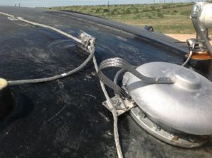
Tank-top piping, thief hatch, and walkway bonding
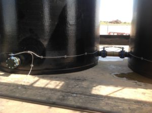
Tank Base and Valve Bonding
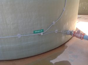
Tank-base piping and carbon veil bonding
2.0 GROUNDING
2.1 For static and lightning protection purposes, flat-bottom metal tanks shall be considered self-grounding (API 545, A.2.1). This applies whether or not a containment liner or barrier is in or under the tank (API, A.2.2). If a steel tank is installed on an insulating base, such as Styrofoam blocks, it shall not be considered to be self-grounding. these tanks shall be grounded to NFPA 780, 7.3.72 (1) or (3).
2.2 If a grounding grid is installed at a site, each structure at that site shall be bonded thereto either individually or through the site bonding system.
2.3 On fiberglass tanks, all metal objects shall be bonded together, and that bonded mass shall be further bonded (grounded) to the site bonding system. A steel tank may be used as ground for a adjacent tanks or other bonded metal masses (API 545, 3.6).
2.4 Conductive piping, walkway handrails, tanks, etc. a minimum of 0.064” thick shall be permitted to be used as main, down, and bonding conductors.
2.5 Additional grounding electrodes (NFPA 780, 4.13) may be installed for supplemental grounding. A reasonable location for supplemental grounding is at the bottom of stairways and ladders, as this may also provide a measure of personnel protection. Supplemental grounding by means of driven ground rods neither decreases nor increases the probability of a direct lightning strike, nor does it reduce the possibility of ignition of the contents in the event of a direct lightning strike (API 2003, 5.4.1).
2.6 Conductors may be routed over a containment berm to supplemental grounding electrodes located outside the berm.
2.7 Metallic piping buried for a length of over 10’ may be substituted for a ground rod.
2.8 Grounding for purposes other than lightning and static protection is not addressed herein, but should be considered by the operator.
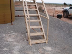
Stairway Grounding
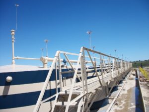
Streamer Delaying Air Terminals on handrail, piping and Enardo Valve
3.0 IN-TANK STATIC CONTROL – Lightning master In-Tank Static Drain (ITSD)
To read the remainder of the article – click here. LMC production facility protection (003)
Notes:
Many sites protected by this type of lightning protection system have sustained direct and nearby lightning strikes without suffering damage. The likelihood of ignition of a site by a direct or nearby lightning stroke or arcing is primarily dependent of the presence or absence of a flammable mixture available for ignition. Therefore, steps should be taken by the operator to discourage the presence of such a mixture. Such steps may include keeping thief hatches closed, installing vapor recovery units (VRU), etc.
NFPA 780, 7.2.1.1 states that openings where flammable concentrations of vapor or gas escape to the atmosphere shall be closed or otherwise protected against the entrance of flame. This indicates that flame arrestors may be required at certain openings. This is the responsibility of the owner/operator at initial site construction, and is not included in this lightning protection system.